Introduction:
A speed-reducing device with multiple gears is a transmission. The arrangement of gears and shafts that transmits engine power to the tractor wheels may be referred to as such. The system comprises multiple components that move the tractor forward and backward to accommodate diverse field conditions. Power train refers to the entire power transmission from the engine to the wheels.
In an agricultural tractor, the transmission case is mounted on the back portion of the vehicle body, while the engine is mounted on the front portion. A propeller shaft connects the transmission case’s input shaft to the engine’s output shaft. A device for changing the speed is located inside the transmission case.
There is a wide range of torque and speed requirements when moving the vehicle/tractor in the field or for transporting. The following is a list of the requirements for a transmission system:
- To lower the engine’s rpm before it reaches the wheel.
- To provide a reverse gear to shift the rotation’s direction.
- Based on the field requirement or the task being conducted, to deliver the necessary torque or speed.
- To offer a neutral position from which the power from the engine can be severed from the drivetrain.
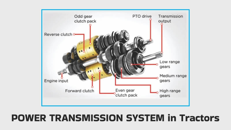
The power transmission system consists of:
The following components are typically found in power transmission systems:
1. A clutch is a mechanism that joins or separates two torque-transmitting components.
2. Transmission – An apparatus for transferring power at various speeds and torques.
3. PTO Drive – The components that transfer torque from the tractor’s engine to the PTO spline at the back.
4. Differential – The component that permits the two wheels on an axle to revolve at various speeds and is typically located in the axle housing.
5. Brake – The mechanism that stops the tractor’s motion, often located in the axle housing.
6. Axle- The shaft and related components that transfer torque from the differential or last gear reduction to the wheels.
How power is transferred from the Engine to the Drive wheels?
- Engine – Crankshaft
- Crankshaft – flywheel
- flywheel – clutch
- clutch – transmission box
- transmission box – differential
- differential – final drives
- final drives – axle
- axle–drive wheels
Tractor transmissions can be divided into the following categories:
1. Fixed-ratio, selectable gear
2. A planetary selector with a fixed ratio.
3. Series of planetary gears
4. Hydrodynamic
5. Hydrostatic
This categorization can be varied. The power and speed of the engine are converted by all transmissions into a more practical combination of torque and speed at the driving wheels.
The potential maximum drawbar power of a tractor is an almost constant independent of the forward speed because the maximum speed is controlled by a governor, with the exception of the lowest speeds when the maximum power is constrained by traction.
Clutch and Fluid Coupling Clutch:
A clutch is a tool that connects and detaches the tractor engine from the drive wheels and transmission gears. Through friction between the driving and driven members, the clutch transmits power.
Tractor clutches are necessary:
In a tractor, a clutch is necessary for the following reasons: The engine has to be started with a proper tool. A proper clutch isolates the engine from the rest of the transmission unit for simple cranking. The clutch is activated after starting the engine to transfer power from the engine to the gearbox. The gearbox needs to be isolated from the engine power while changing gears in order to prevent damage to the gear teeth and imperfect gear engagement. A clutch handles this work.
The tractor’s belt pulley needs to be halted while it is operating in the field, but the engine must remain running. A clutch accomplishes this.
Final Drive and Differential Unit:
Differential Unit: A differential unit is a unique set of gears that enables one of the tractor’s rear wheels to rotate more slowly or more quickly than the other. The inner wheel must travel a shorter distance while turning the tractor on a curved path for it to move faster than the other at the turning point. An end-mounted bevel pinion is included on the output shaft that exits the gearbox. The crown wheel, a sizable bevel wheel, and the bevel pinion are meshing together. The primary purposes of a crown wheel assembly are I power transmission through right angle drive to fit tractor wheels, and (ii) balancing the wheels.
(ii) to slow the rotational speed.
Final Drive: A gear reduction component in the power trains located between the differential and the drive wheels is the final drive. The power is finally transferred to the wheels and rear axle by final drive.
The drive is provided via a pair of spur gears instead of being directly connected to the half shafts that drive the tractor’s rear wheels. Each half shaft has a small gear at the end that engages with bull gear, a larger gear. The tractor’s back wheel is carried by the bull gear, which is positioned on the shaft. The final drive mechanism is the name of the device for final speed reduction that is appropriate for tractor rear wheels.
Brake and Steering System: The steering system of a tractor controls the angular movement of the front wheels. By using leverages, this system steering wheel reduces the operator’s effort required to spin the front wheel. The steering system is made up of the following parts: the steering wheel, the steering shaft, the steering gear, the pitman arm (drop arm), the drag link, the steering arm, the tie rod, and the kingpin.
When the driver turns the steering wheel, a series of gears in the steering shaft converts the motion to an angular movement of the pitman’s arm.
The drag link and tie rods further convey the angular movement of the pitman’s arm to the steering arm. The steering arms are connected to the corresponding kingpins, which are an essential component of the stub axle that houses the wheels. The front wheel’s angular movement is influenced by how the steering arm moves.
Brake: A tractor’s motion can be stopped or slowed down using the brake. Two independent pedals are used to control it, and it is positioned on the drive axle. To aid the tractor’s turning while working in the field, each pedal can be used independently or locked together using a lock.
Hydraulic Control System: It is a mechanism in a tractor that uses hydraulic power to raise, hold, or lower mounted or semi-mounted equipment.
Belt Pulley: A belt pulley is included with every tractor. The pulley’s job is to use a belt to transfer power from the tractor to stationary machinery. It is used to run many devices, including threshers, centrifugal pumps, silage cutters, and more. The tractor’s pulley might be found on the left, right, or backside. A clutch is used to engage or disengage the pulley drive from the engine. Cast iron is typically used to make the pulley.
For more details about tractor, tractor price, tractor video, tractor games visit khetigaadi mobile application.